The WJ-8716, WJ-8718, AN/URR-74(V) & WJ-8709 radio can be fitted with three different Spectrum Monitor Outputs at two different frequencies, 455 kHz and 10.7 MHz. The 455 kHz option is the most common. The SMO output is typically a BNC jack added above the fuse holder.
|
|
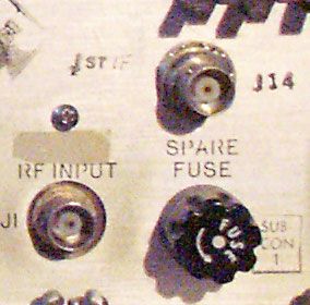
The picture on the left is the for the relatively common
SMO option (labeled "1st IF"), which is a 455 kHz
output with a bandwidth of 30 kHz. |
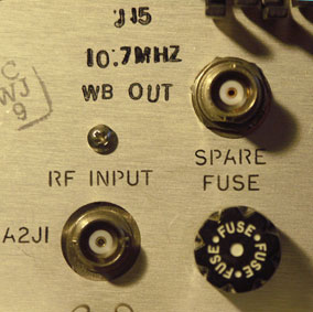
The picture on the right is for the wideband IF output, which is a 10.7 kHz output with a bandwidth of 30 or 100 kHz depending on the first converter filter in the radio.
|
|
The standard SMO option manual covers all the circuitry found in both the 455 kHz and 10.7 MHz IF outputs. The SMO option manual covers the 455 kHz output which uses a matching network and a converter board. The 10.7 MHz outputs use the same matching network (the 796031 or 796031-1 in the manual).
back to top
|
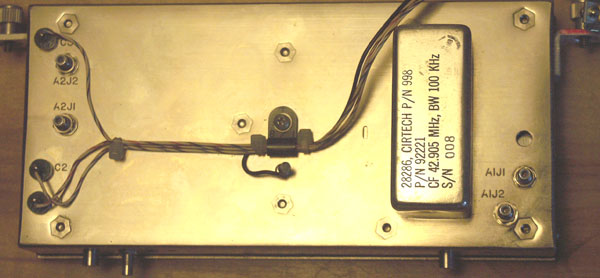 |
The input converter module contains the circuitry that takes the RF input and converts it twice, to first IF of 42.905 MHz and the second IF of 10.7 MHz. (the receivers 455 kHz conversion occurs elsewhere). If your receiver has the SMO output or you wish to add it, the circuitry is inside this box.
back to top
|
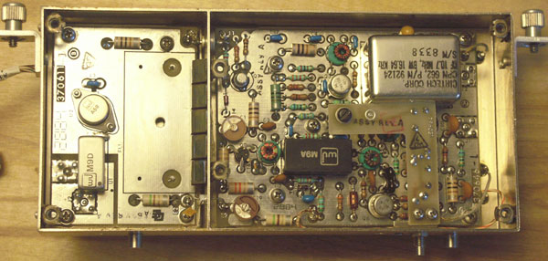 |
The inside of the input converter is divided into two compartments. The left compartment is the first or "up" converter, which moves the signals up to be centered on 42.905 MHz. The right compartment is the second converter stage, which moves the signal down to be centered at 10.7 MHz.
back to top
|
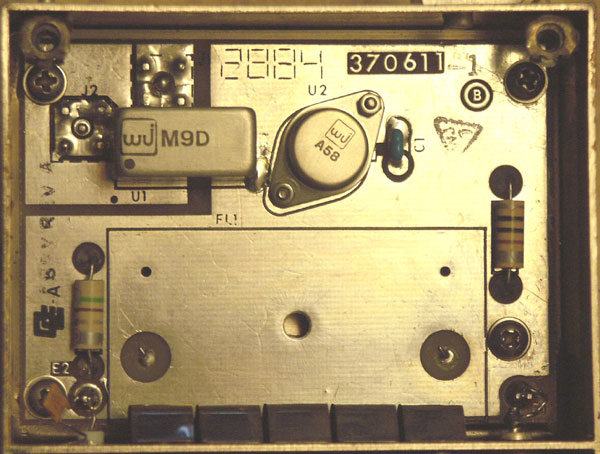 |
This is a special first converter stage. Normally a 30 kHz wide filter centered at 42.905 MHz is installed along the bottom edge of this compartment. This radio has a special 100 kHz wide front end, which is mounted on the outside of the case (see two photos up). In this radio, the discrete transistor input circuitry in this radio has been replaced by a monolithic WJ wideband amplifier (labeled with the model number "A58" ). The rectangular silver can near at the upper left, labeled "M9D", is the input mixer - the device most commonly damaged by static or lightning discharge.
back to top
|
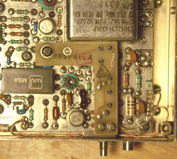 |
This close up of the 2nd converter box shows the 796031 matching network (inverted L shaped board, solder side up) installed. The board is supported by a clip that snaps over transistor Q4 and the SMB connector extending out the edge (bottom, when installed). This SMB connector is visible from the bottom of the radio when the cover is off (picture here). This installation is done without soldering as the collector of Q4 is the case and the matching network gets the IF signal directly through the mounting clip.
|
Adding this board to your WJ-8716, WJ-8718 or AN/URR-74(V) will give you a 10.7 MHz IF pre-filter IF output. The board is a simple device to construct. See the SMO option manual for a circuit board layout, schematic and parts list.
|
There are two versions of this matching network. The 796031 is the older version (shown), but necessary if you need more than 30 kHz of bandwidth (which you can only get if your first converter filter is also wider than 30 kHz). The 796031-1 is a narrower matching network using a ceramic filter to provide an additional 30 dB suppression of the 2nd local oscillator signal.
back to top
|
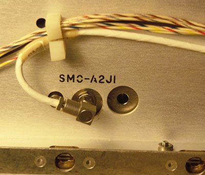 |
If you see this jack inside your radio from the bottom, your input converter already has a 10.7 MHz IF output. The bandwidth will probably be 30 kHz, unless you can see an external filter on the body of the input converter
back to top |
|