(Articles by collectors on how-to, repairs and projects)
|
|||
| WJ-CEI Home Page | My Publications | Research Material Donations | Bio and Contact |
| Collector Corner (Articles by collectors on how-to, repairs and projects) |
|||
Communication Electronics Technology |
| WJ-CEI Receivers & Tuners | WJ-CEI Signal Monitors | WJ-CEI History | WJ-CEI Catalogs |
| WJ-CEI Surveillance Systems | WJ-CEI System Accessories | WJ-CEI Related History | WJ-CEI Resources |
WJ-8617 Receiver Series |
| NOTE: There are significant differences between the plain, A, B and B(S1) versions of this radio. (Testing for an S1) | |
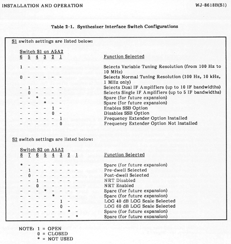
Option switches for the S1 version only - S1 versions are listed in the configuration guide. |
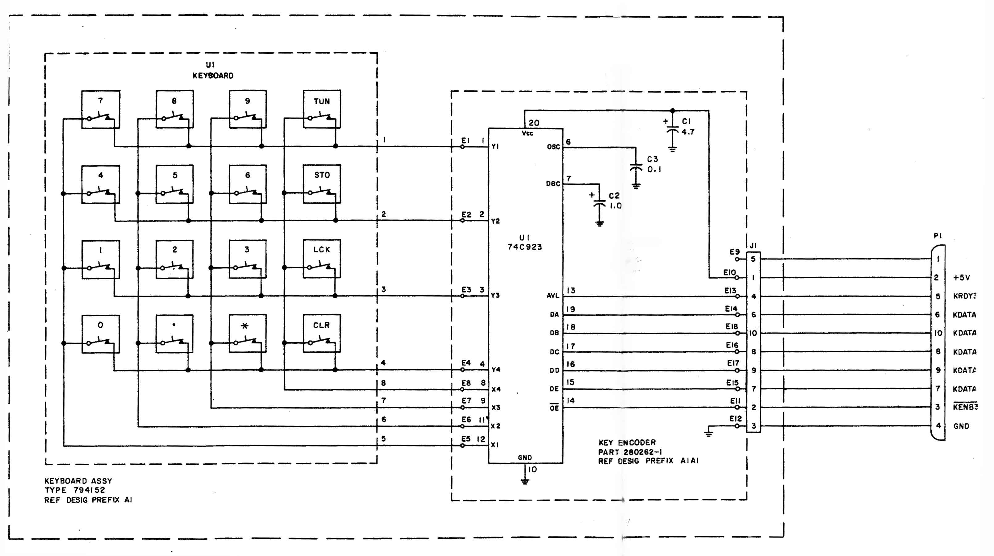
Pluggable Keypad Controller (PKC) schematic |
| WJ-8617B-8 | WJ-8617B-17 | WJ-8617B-26 |
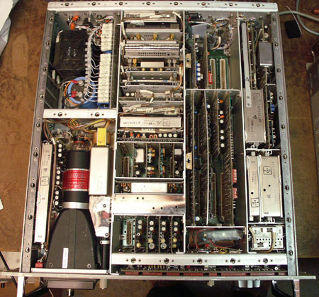
| Comparison of 3 versions | inside view of WJ-8617B | rear panel of WJ-8617B |
| The WJ-8617 (and WJ-8618) are one of the more successful and relatively common WJ VHF-UHF receivers. They were produced in a bewildering array of versions with many different options. It is very difficult to know what you are getting when you buy one of these radios unless you know them well and do a thorough external and internal inspection. The radios have a flexible architecture and were often reconfigured in the field. Caveat emptor! |
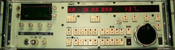 |
This is a WJ-8617B-8. The green color is rumored by collectors to be "spare green" to make a backup radio stand out when substituted in a rack. The records are not clear for this radio, but the green colored front panel was also used on orders fro Sylvania and E-Systems. This radio has the VLF convertor option. It is one of only two versions with this option. The VLF convertor is switched in below 6 MHz. This radio is also a 10 IF unit with IFs of 3.2, 10, 20, 50, 200, 400, 800, 1200, 1600, and 3200 kHz. It also has the SSB option which additional 3.2 kHz upper and lower sideband filters in the 455 kHz SSB IF stages. The other 10 IF filters are in the 21.4 MHz IF chain. This radio works fine despite appearances in the picture. The front LED displays are strobed and don't always show up when photographed with a fast shutter speed. See the WJ-8617 series guide for more details. |
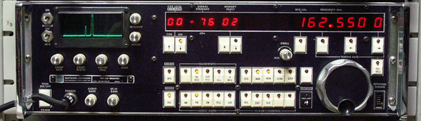 |
This is a WJ-8617B-17. This is an S1 series radio. It has an LNA instead of a antenna switch at the input stage. It came stock with the FE option, raising the top end of reception to 1100 MHz. This one has the synthesizer EPROM changed to allow it to tune to down to DC. This radio is a hot receiver in VHF/UHF service but overloads so badly below 30 MHz that it is unusable. This radio has bandwidths of 50 & 250 kHz, 1 & 4 MHz (shown). I changed it to 20, 50, 200 & 500 kHz, 1 MHz and added the SSB option card with 3.2U and 3.2L kHz bandwidths. See the WJ-8617 series guide for more details. Spencer Bahner has written a short article on how to remove the preamplifier stages, which significantly degrade performance in urban and high RF environments. The article on the preamp removal is here. |
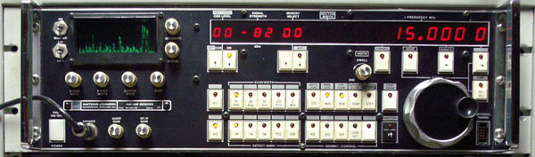 |
This is a WJ-8617B-26. It is a special modification of the late model S1 series with an upconverter allowing coverage from 10 kHz to 500 Mhz. Most WJ-8617 (and 8618) receivers were VHF/UHF radios covering 20-500 MHz in basic form. This radio offers great performance throughout the 10 kHz to 500 MHz range. It has bandwidths of 3.2U, 3.2L, 6.4, 10, 20, 50, 250 kHz (2 MHz was installed instead of 250 kHz when this picture was taken). See the WJ-8617 series guide for more details. |
Comparison of these three versionsThese three radios have very different capabilities but to the untrained eye, they appear identical (except for the green color). The WJ-8617B-8 and WJ-8617B-26 offer excellent VLF/LF/HF functionality. Many versions could tune down to 2 MHz (HFE option) or DC (LFE option) but these offered no input filtering or in some cases, only a 30 MHz low pass filter when tuned below 20 MHz. The VLF option is typically not listed on the rear panel. It is also found in the WJ-8617B-18 and WJ-8617B-20. See the WJ-8617 series guide for more details. Testing for an S1 versionYou can do a power on test to see if a WJ-8617B radio is an S1 version. Simply depress and hold the MAN button as you turn the power on. It will display the model with version number. The other versions will not respond to this sequence.\ |
The WJ-8617B-17 was the only version with the LNA front end. The basic chassis supports either version but their main features cannot coexist in the same radio. The VLF converter in the -26 occupies the same slot as the FE option in the -17. The 10 IF option radios are very desirable. There were not many radios made that can support ten IF bandwidth (pre-DSP). Dual IF and demodulator cards cannot be mixed with single IF cards in the same radio. |
These radios are jammed full of electronics. They feature motherboard-card cage construction and are relatively easy to service because they are full of 74xx TTL logic and have very few specialized integrated circuits. |
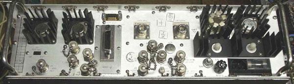 |
The rear panel highlights the amazing versatility of these radios. This one has many options, GPIB remote interface, BITE (Built-In Test Equipment), DRD (Digitally Refreshed Display) and more. When buying one of these radios, always check to see the option cards are installed. These radios have an open platform design and option cards can be swapped. About 1/3 of the options in the plain and A and B series are simple card swaps. Almost all the options are simple card swaps in the S1 series. |