
|
|||
| WJ-CEI Home Page | My Publications | Research Material Donations | Bio and Contact |
Communication Electronics Technology |
| WJ-CEI Receivers & Tuners | WJ-CEI Signal Monitors | WJ-CEI History | WJ-CEI Catalogs |
| WJ-CEI Surveillance Systems | WJ-CEI System Accessories | WJ-CEI Related History | WJ-CEI Resources |
WJ-9205 Signal Monitor |
| Front | Inside | Back | A Rare CRT |
| WJ-9205 & WJ-9206 data sheet | WJ-CEI Spectrum Display guide | ||
 |
|||||||||||||||||||||
|
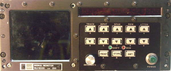
The WJ-9205 Signal Monitor can display up to three traces simultaneously from up to three different receivers with each trace at a different sweep width. A 21.4 MHz unit with -100 dBm sensitivity. Sweep widths available are 50, 100, 200 & 500 kHz and 1, 2 & 5 MHz. Standard resolution is 10 kHz. Options include 2 kHz resolution and a IEEE-488 interface. |
|||||||||||||||||||||
 |
|||||||||||||||||||||
|
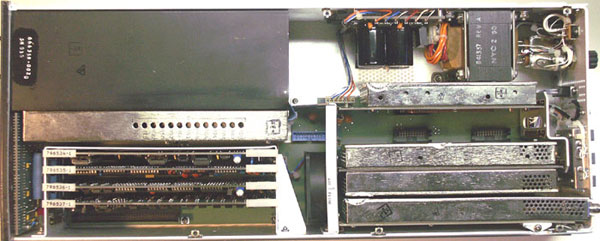
The inside is tight but cleanly laid out. |
|||||||||||||||||||||
 |
|||||||||||||||||||||
|
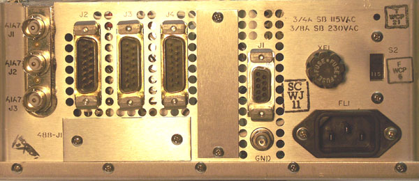
The back has blank plates for options. The three DB-15s labeled J2, J3 & J4 only have two wires connected to each, presumably to interface with WJ-8615P receivers, for which this unit was originally designed. J1 provides for X-Y outputs or X-Y inputs, which can be selected from the front panel. |
|||||||||||||||||||||
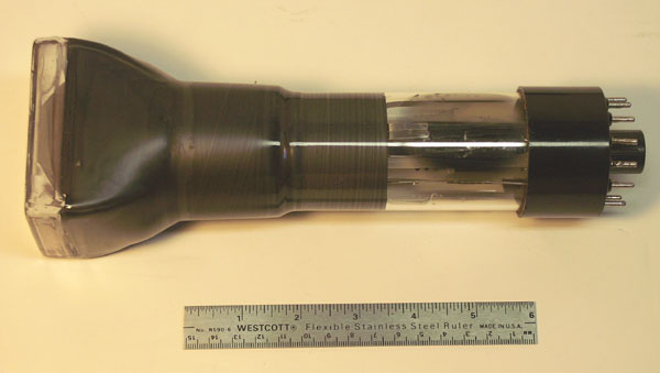
The sad storyThe replacement tube for these SMs is listed as the Thomas 4E35P31, a very rare CRT. The original tube is a Magnavox D1062P31 (General Atronix Division). Replacements are all but impossible to find. Google draws a blank on the Magnavox tube. The Thomas tube pops up a few references. Thomas will rebuild your tube, for $1000. The US Defense Supply Center placed a request for pricing on this CRT with an NSN of 5960-01-350-2925, so there may be some floating around the system. The X-Y signals are available on the rear panel in J1, if you happen to get one with a dead CRT. It will drive a Tektronix 604 display nicely with some minor adjustments to the X and Y amplitudes. The pinout of J1 is: |
|||||||||||||||||||||
|
If you see one of these or know of a usable substitute, please let me know. | ||||||||||||||||||||
|
|||||||||||||||||||||