|
|||
| WJ-CEI Home Page | My Publications | Research Material Donations | Bio and Contact |
Communication Electronics, Inc |
Bethesda and Rockville, Maryland |
| CEI Main Page | CEI Receivers | CEI History | CEI Related History | CEI Documents |
| CEI-WJ receivers and tuner guide |
CEI-WJ surveillance system guide |
CEI-WJ spectrum display guide |
WJ- CEI Receivers |
CEI 901-1 Receiver |
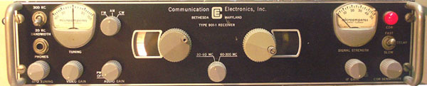 |
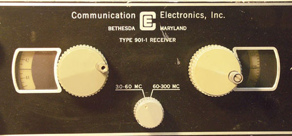
901-1 front panelThe 901 was the first, if not the first VHF receiver CEI brought to market. It is a remarkably quiet and stable radio, especially considering it is an early 1960s design using all vacuum tubes. The 901-1 pictured on this page has a carrier operated relay (COR) not found on the plain 901. The early pedigree is obvious from the roundish gray meters made by Marion Instruments (Honeywell). The performance of this radio is head and shoulders above anything else produced at that time, especially at its size and weight. It has excellent sensitivity and low noise because of cutting edge design using 7077 ceramic planar vacuum tubes in the upper band tuner (60-300 MHz). The use of nuvistors in the low band tuner and throughout the remaining stages resulted in low power usage and heat production which resulted in superior frequency stability. The superior stability is also due to the Mallory Inductuners in the RF stages. The Inductuners were used with beautifully designed anti-backlash gear trains and spiral dials in moving windows. The tuning mechanisms, dials, and choice of ceramic planar vacuum tubes bear a striking resemblance to the Nems-Clarke 1906, but the rest of the 1906 lags a generation behind. |
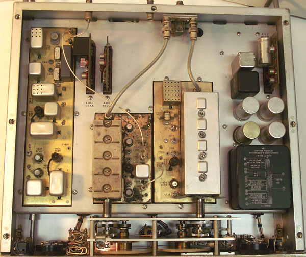 |
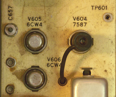
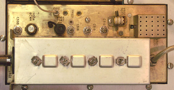
901-1 top insideThe inside of the 901-1 reveals several design features that would remain consistent throughout CEI and eventually WJ equipment. Clean, uncluttered layout, gold colored sub chasses, nuvistors, ceramic planar tubes, cutting edge solid-state devices (in the power supply only - early germanium transistors and diodes), compact packaging and the highest quality assembly standards were hallmarks of their designs. |
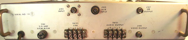 |
901-1 rear panelThe rear panel is simple, but has several features that were uncommon in the mid-sixties, the carrier operated relay (COR), a squelch like feature that turned on external tape decks or equipment and a spectrum monitor (SM) output, a wideband pre-IF filter output at 21.4 MHz. I don't know how the 21.4 MHz IF frequency was chosen but it either started with CEI or late Nems-Clarke equipment. If anyone knows, I'd love to hear the history. Please contact me using the address on my home page. |
 |
901-1 tuning dialsThe tuning dials on the 901 are spiral scales printed on 1/8" thick translucent plastic. They were illuminated from behind. A small crescent window tracked the spiral showing on the relevant part as the radio was tuned. This dial mechanism was very similar albeit a simpler and more elegant design than older Nems-Clarke radios, particularly the 1906 and 1907. |
 |
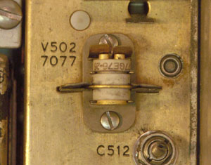
901-1 receiver - high band (60-300 MHz) tunerThe spiral tuning dials were used in conjunction with tuners based on Mallory Inductuners. The Inductuner was a significant leap forward in the design of stable VHF and UHF radios. The small pair of 7077 ceramic planar triodes gave this radio a very quiet front end, a substantial edge on the competition for the time. The rest of the active devices in the tuners were all nuvistors. This tuner was designed by Peter Pao, one of the original CEI staff who left Nems-Clarke with Ralph Grimm. |
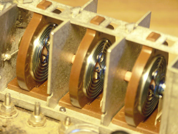 |
Mallory Inductuner internal viewThe Mallory Inductuner consists of ganged decks of spiral inductors. If you are rebuilding one of these radios, do not attempt to clean these spirals unless you have the proper conducting lubricant to replace what you remove. The original compound is blue, but I have been told the factory used General Cement (GC) "tuner lube" part no. 10-2610 for rebuilds about 15 years ago. |
|
|
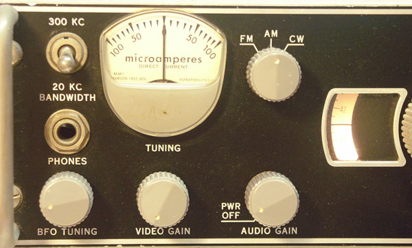 |
901-1 front panel - left closeup viewThis is left end of the front panel. The 20 kHz and 300 kHz IF bandwidth are fairly typical for this time period. The radios were sometimes ordered with different IF filter. These units would have a different dash number following the model number. The Marion Instrument meter is unusual. This is the only radio I have seen with this style of meter. Mid production units used square framed Simpson meters and the last runs used Simpson Clear Vue meters. The gray Raytheon knobs were ubiquitous on early CEI equipment. They were replaced by black Raytheon knobs after Watkins Johnson purchased CEI. |
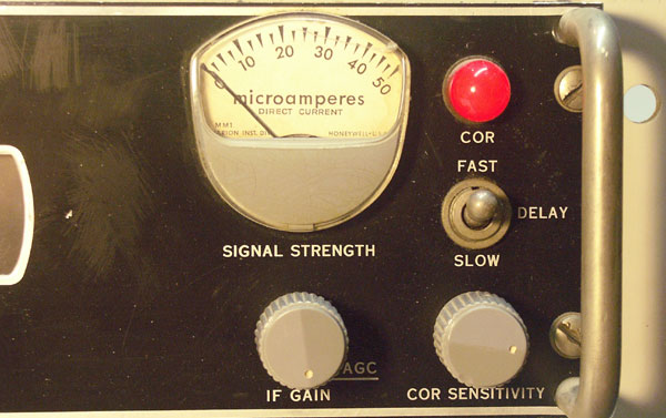 |
901-1 front panel - right closeup view - COR (Carrier Operated Relay)The right end of the front panel shows the Carrier Operated Relay (COR) controls and indicator. This is a squelch circuit that allowed the receiver to operate a tape machine to record audio only when a signal was present. You could leave the radio and recorder to gather signals unattended. |